目录
•1.版本信息
•2.电子齿轮所有ID
•3.使用案例
•3.01 新建项目
•3.02 测试基本CAM
•3.03 启动、停止、重新耦合 电子齿轮
•3.04 启动位置及间隔ID504,ID505
•3.05 主轴附加轴,从轴附加轴
•3.06 电子凸轮曲线 预定义曲线
•3.07 电子凸轮曲线 Profile编辑
•3.08 电子凸轮曲线 Poly编辑
•3.09 基本补偿模式
•3.10 第一个State需要注意的地方(补偿模式下自动计算的路径可能不同)
•3.11 补偿模式的计算方法
•3.12 如何实现以下曲线 ?
•3.13 如何在线修改参数保证周期一致性
•3.14 电子齿轮Restart
•3.15 反向运动
•3.16 补偿模式的速度加速度限制
•3.17 ID128限制功能
版本信息 |
修改内容 |
修改人 |
修改时间 |
V1.00 |
创建 |
刘柏严 |
2017.03.02 |
V1.01 |
补充目录,调整格式 |
袁志毅 |
2022.07.27 |
Parameter ID name |
Access |
Data type |
Value range |
Init value |
Description |
CMD_AUT_START |
WR |
UI2 |
|
|
Cam automat: Command |
CMD_AUT_ABS_MOVE |
WR |
I4 |
|
|
Cam automat: Start movement with absolute target position [units] 与普通的ABS move效果一样 |
AUT_START_ST_INDEX |
WR |
UI1 |
0 ... 14 |
0 |
Index for the Start state |
AUT_CAM_MA_S_REL |
WR |
I4 |
|
0 |
Relative master position in the cam profile [units] |
CMD_AUT_ST_CHECK |
WR |
UI1 |
0 ... 14 |
|
Cam automat: Check parameter set for an automat state |
AUT_DATA_INDEX |
RD, WR |
UI2 |
1 ... 20 |
|
Transfer index for cam profile data |
AUT_POLY_DATA |
RD, WR |
DATA |
|
|
Cam profile polynomial data |
AUT_POLY_CHECK |
WR |
UI2 |
1 ... 64 |
|
Check cam profile polynomial data |
AUT_MA_AXIS |
WR |
UI2 |
<ParID> |
0 |
Parameter ID of the master axis |
AUT_MA_ADD_AXIS |
WR |
UI2 |
<ParID> |
0 |
Parameter ID of the additive master axis |
AUT_SL_ADD_AXIS |
WR |
UI2 |
<ParID> |
0 |
Parameter ID of the additive slave axis |
AUT_SL_FACTOR_ID |
WR |
UI2 |
<ParID> |
0 |
Parameter ID for multiplication factor of the slave axis |
AUT_EVENT_ID1 |
WR |
UI2 |
<ParID> |
0 |
Parameter ID for event input |
AUT_SL_LATCH_ID |
WR |
UI2 |
<ParID> |
0 |
Parameter ID for the latch value of the slave axis |
AUT_S_START_MODE |
RD, WR |
UI1 |
0, 1 |
0 |
Mode for event type ncS_START and ncS_START_IV1..4 |
AUT_MA_S_START |
WR |
I4 |
|
0 |
Start position of the master axis [units] |
AUT_MA_IVSTART |
WR |
UI4 |
|
1677216 |
Start interval for the master axis [units] |
AUT_MA_S_START_IDX |
WR |
UI1 |
1 ... 4 |
1 |
Index for relative start position of the master axis within interval |
AUT_MA_S_START_IV |
WR |
I4 |
0.. |
0 |
Relative start position of the master axis within interval [units] |
AUT_MA_V_MAX |
WR |
R4 |
|
1.0 |
Maximum speed of the master axis [units/s] |
AUT_ST_INDEX |
WR |
UI1 |
0 ... 14 |
0 |
Index of a parameter set for a state |
AUT_ST_DATA_INDEX |
WR |
UI2 |
0 ... 14; |
0 |
Index of cam profile data for one state |
AUT_MA_ID |
WR |
UI2 |
<ParID> |
0 |
Parameter ID of the master axis for a state |
AUT_MA_FACTOR |
WR |
I4 |
>0 |
1 |
Multiplication factor for the master axis |
AUT_SL_FACTOR |
WR |
I4 |
|
1 |
Multiplication factor for the slave axis |
AUT_ST_COUNT_INIT |
WR |
UI2 |
|
0 |
Start value state repeats for the ncCOUNT event |
AUT_ST_COUNT_SET |
WR |
UI2 |
|
0 |
Counter state repeats for the ncCOUNT event |
AUT_MA_CAM_LEADIN |
WR |
I4 |
>= 0 |
0 |
Relative entry distance of master axis within the cam profile [units] |
AUT_COMP_MODE |
WR |
UI1 |
|
ncOFF |
Compensation gear mode |
AUT_COMP_MA_S |
WR |
I4 |
|
1 |
Compensation distance for the master axis [units] |
AUT_COMP_SL_S |
WR |
I4 |
|
0 |
Compensation distance for the slave axis [units] |
AUT_COMP_MA_S_MIN |
WR |
I4 |
|
1 |
Minimum compensation distance for the master axis [units] |
AUT_COMP_SL_S_MIN |
WR |
I4 |
|
-231+1 |
Minimum compensation distance for the slave axis [units] |
AUT_COMP_SL_S_MAX |
WR |
I4 |
|
231-1 |
Maximum compensation distance for the slave axis [units] |
AUT_COMP_SL_V_MAX |
WR |
R4 |
|
|
Maximum speed of the slave axis in the compensation [units/s] (initialized with AXLIM_V_POS respectively BASIS_MOVE_V_POS_VAX1) |
AUT_COMP_SL_V_MIN |
WR |
R4 |
|
0 |
Minimum speed of the slave axis in the compensation [units/s] |
AUT_COMP_SL_A1_MAX |
WR |
R4 |
|
|
Maximum acceleration of the slave axis in compensation phase 1 [units/s2] |
AUT_COMP_SL_A2_MAX |
WR |
R4 |
|
|
Maximum acceleration of the slave axis in compensation phase 2 [units/s2] |
AUT_COMP_SL_T_JOLT |
WR |
R4 |
|
0 |
Jolt time of the slave axis in the compensation [s] |
AUT_EV_INDEX |
WR |
UI1 |
0 ... 4 |
0 |
Index of a parameter set for an event |
AUT_EVENT_TYPE |
WR |
UI1 |
|
ncOFF |
Event type |
AUT_EVENT_ATTR |
WR |
UI1 |
|
ncAT_ONCE |
Event attribute |
AUT_EVENT_ACTION |
WR |
UI4 |
|
0 |
Action at state transition |
AUT_EVENT_ST_INDEX |
WR |
UI1 |
0 ... 14, 255 |
0 |
Index for the next state |
AUT_STATUS |
RD |
UI1 |
0, 1, 3 |
0 |
Status |
AUT_ACT_ST_INDEX |
RD |
UI1 |
0 ... 14, 255 |
255 |
Index for the current state |
AUT_ACT_CAM_TYPE |
RD |
UI1 |
0, 1 |
0 |
Cam type for the current state |
AUT_ACT_ST_DAT_IDX |
RD |
UI2 |
0 ... 14; |
0 |
Index of cam profile data of the actual state |
AUT_ST_EV_COUNT |
RD |
UI4 |
|
0 |
State transition count |
AUT_EV_STATUS_BITS |
RD |
UI4 |
|
0 |
Event status bits |
AUT_S_SET |
RD |
I4 |
|
|
Set position [units] |
AUT_S_SHIFT_START |
RD |
I4 |
|
0 |
Shift of the position on the cam automat output at the start [units] |
AUT_MA_CAM_REL |
RD |
R4 |
|
0 |
Relative master position within the current cam profile or compensation curve [units] |
AUT_MA_CAM_OFFSET |
RD |
I4 |
|
0 |
Cam offset of master axis [units] |
AUT_SL_CAM_OFFSET |
RD |
I4 |
|
0 |
Cam offset of slave axis [units] |
AUT_SL_S |
RD |
I4 |
|
0 |
Position of slave axis before the additive element [units] |
AUT_SIGNAL_SET |
WR |
UI1 |
|
|
Signal set |
AUT_SIGNAL_RESET |
WR |
UI1 |
|
|
Signal reset |
AUT_ONL_PAR_LOCK |
RD, WR |
UI1 |
0, 1, 2 |
0 |
Lock for consistent online parameter change in parameter and curve download |
ONL_PAR_LOCK |
WR |
|
|
|
Lock for consistent online parameter changes of drum sequencer and cam profile |
AUT_TRIG1_T_DELAY |
RD, WR |
I4 |
-20000.. |
0 |
Trigger1 delay time [ms] |
AUT_TRIG2_T_DELAY |
RD, WR |
I4 |
-20000.. |
0 |
Trigger2 delay time [ms] |
AUT_MODE_BITS |
RD, WR |
UI4 |
0 ... 7 |
0 |
Control bits for function mode |
AUT_MSG_MODE_BITS |
RD, WR |
UI4 |
0 ... 3 |
|
Messaging mode control bits |
AUT_PAR_RESET |
WR |
UI1 |
0 ... 14, 255 |
|
Reset parameter to initial values |
SGEN_SW_END_IGNORE |
RD, WR |
UI1 |
0, 1, 2, 3 |
0 |
Ignore SW limits |
AUT_MOVE_CONF_IDX |
RD, WR |
UI1 |
0 ... 4 |
0 |
Cam automat: Index of parameter record of move configuration |
MOVE_CONF_IDX |
RD, WR |
UI1 |
2 ... 4 |
|
Move configuration: Index of parameter record |
MOVE_CONF_V_POS |
WR |
R4 |
|
|
Maximum speed in positive direction [units/s] |
MOVE_CONF_V_NEG |
WR |
R4 |
|
|
Maximum speed in negative direction [units/s] |
MOVE_CONF_A1_POS |
WR |
R4 |
|
|
Maximum acceleration in positive direction [units/s2] |
MOVE_CONF_A2_POS |
WR |
R4 |
|
|
Maximum deceleration in positive direction [units/s2] |
MOVE_CONF_A1_NEG |
WR |
R4 |
|
|
Maximum acceleration in negative direction [units/s2] |
MOVE_CONF_A2_NEG |
WR |
R4 |
|
|
Maximum deceleration in negative direction [units/s2] |
1 |
||||||||||||||||||||||||||||||||||||
1 |
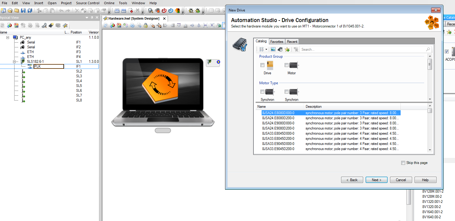
新建仿真项目 |
|||||||||||||||||||||||||||||||||||
2 |
添加powerlink接口卡
|
|||||||||||||||||||||||||||||||||||
3 |
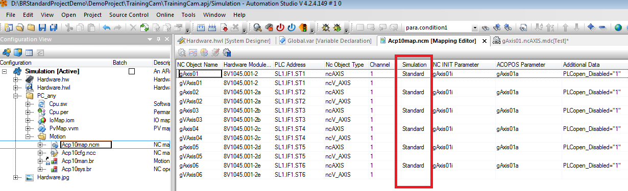
修改ncmap
|
|||||||||||||||||||||||||||||||||||
4 |
添加轴控任务,配置任务周期,添加参数表。 |
|||||||||||||||||||||||||||||||||||
5 |
Test 轴是否正常工作 |
|||||||||||||||||||||||||||||||||||
2 |
||||||||||||||||||||||||||||||||||||
|
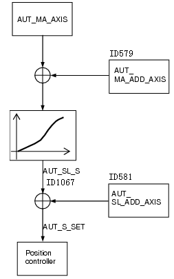
基本参数层次关系 •AUT_MA_AXIS Master axis parameter ID ▪RD, WR UI2 <Par_ID> ▪e.g.: actual position of encoder2: PARID_ENCOD2_S_ACT, position of virtual axis: PARID_S_SET_VAX1, network connection1/2: PARID_MA1/2_CYCLIC_POS
•AUT_MA_S_START Start position of the master axis ▪RD, WR I4 [units] ▪Only for state 0 (base state)
•AUT_MA_IVSTART Start interval for the master axis ▪RD, WR UI4 [units] ▪Only for state 0 (base state, init value 1)
•AUT_MA_V_MAX Maximum speed of the master axis ▪RD, WR R4 [units/s] ▪To calculate the compensation polynomial (staying within axis limits)
•AUT_ST_INDEX Index of a parameter set for a state ▪WR UI1 ▪State number for parameterization (0-9), 0 = base state
•AUT_ST_DATA_INDEX State index for cam profile data ▪WR UI2 ▪0xFFFF precompiled 1:1 straight line ▪0 Deactivates this state ▪1-10 Index of curve for a state (init value 1) ▪References download data (instead of name)
•AUT_MA_FACTOR Multiplication factor for the master axis ▪WR I4 ▪Stretch factor for the curve master period (> 0). Preset to 1.
•AUT_SL_FACTOR Multiplication factor for the slave axis ▪WR I4 ▪Stretch factor for the curve slave period. Preset to 1.
•AUT_COMP_MODE Compensation gear mode ▪WR UI1 ▪Variants: ncOFF, ncWITH_CAM, ncLATCHPOS, ncONLYCOMP
•AUT_COMP_MA_S Compensation path for the master axis ▪WR I4 [units] ▪Length of the compensation curve on the master side depending on the compensation variant
•AUT_COMP_SL_S Compensation path for the slave axis ▪WR I4 [units] ▪Length of the compensation curve on the slave side depending on the compensation variant
•AUT_EV_INDEX Index of a parameter set for an event ▪WR UI1 ▪Event number to define parameters (0-3)
•AUT_EVENT_TYPE Event type ▪WR UI1 ▪ncOFF, ncS_START(only in state 0), ncST_END, ncCOUNT, ncSIGNAL1-4 ▪ncTRIGGER1, ncTRIGGER2, + ncP_EDGE / ncN_EDGE
•AUT_EVENT_ATTR Event attribute ▪WR UI1 ▪ncAT_ONCE, ncST_END
•AUT_EVENT_ACTION Action at state transition ▪WR UI4 ▪Bit0=1 synchronous parameter transfer after ONL_PAR_LOCK 2 -> 0
•AUT_EVENT_ST_INDEX Index for the next state ▪WR UI1 ▪0-9 Transfer to this state on arrival of the event ▪255 Ends the automat
•AUT_ONL_PAR_LOCK Block for consistent online parameter changes ▪RD, WR UI1 0,1,2 ▪0 No acceptance block active ▪1,2 Acceptance block active, parameter change and curve download ▪1->0 Change accepted at next state transition ▪2->0 Change accepted synchronously during state transition with EVENT_ACTION bit0=1
|
|||||||||||||||||||||||||||||||||||
3 |
||||||||||||||||||||||||||||||||||||
|
•ID502 CMD_AUT_START WR UINT
•用来启动停止电子齿轮,只能等于以下数值 •ncSTART 启动电子齿轮(从state0开始) •ncRESTART如果没有发送过停止电子齿轮命令由于轴报警或发送正反转命令造成电子齿轮关系解除,那么原电子齿轮位置依然存在,可以运动到此位置,发送ncRESTART重新耦合电子齿轮。其他文档有详细解释。 •ncSTOP 停止电子齿轮
|
|||||||||||||||||||||||||||||||||||
4 |
||||||||||||||||||||||||||||||||||||
|
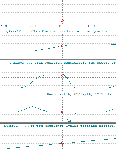
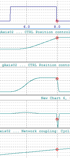
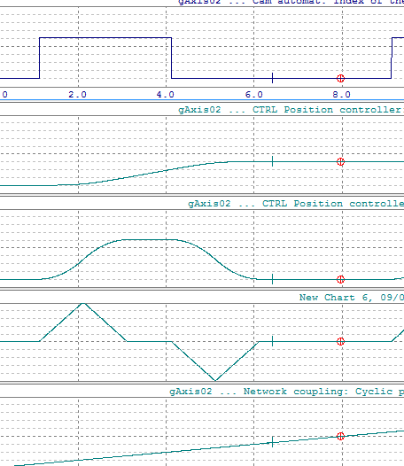
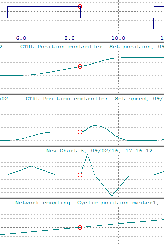
情况1使用ncS_START事件 State0的 ID513 AUT_EVENT_TYPE = ncS_START ID514 AUT_EVENT_ATTR = ncST_END ×错误设置 不会运动到下一个State ID514 AUT_EVENT_ATTR = ncAT_ONCE √正确设置 会运动到下一个State 设置ID504 AUT_MA_S_START 发送CAM_START命令
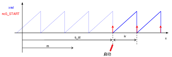
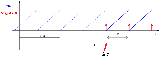
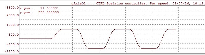
此时如果主轴位置小于启动位置,那么会等待主轴位置到达再启动。
如果主轴位置大于启动位置,那么会在下一个整周期启动。如下图
if ((m - s) > 0) x = s + ((m - s) / iv + 1) * iv ; else x = s ; {0>if ((m - s) > 0)<}0{><0} {0>if ((m - s) > 0)<}0{><0} 情况2使用ncS_START_IV事件 不常用
|
|||||||||||||||||||||||||||||||||||
5 |
||||||||||||||||||||||||||||||||||||
|
|
|||||||||||||||||||||||||||||||||||
6 |
||||||||||||||||||||||||||||||||||||
1 |
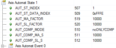
预定义补偿 0xFFFE 使用示例:
入口速比是进入点 出口速比是ID519:ID520 ID519,ID520定义的距离不走。整个State主轴走ID511,从轴走ID512 |
|||||||||||||||||||||||||||||||||||
2 |
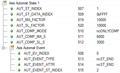
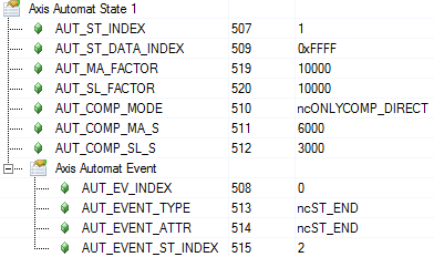
预定义直线 0xFFFF 使用示例:
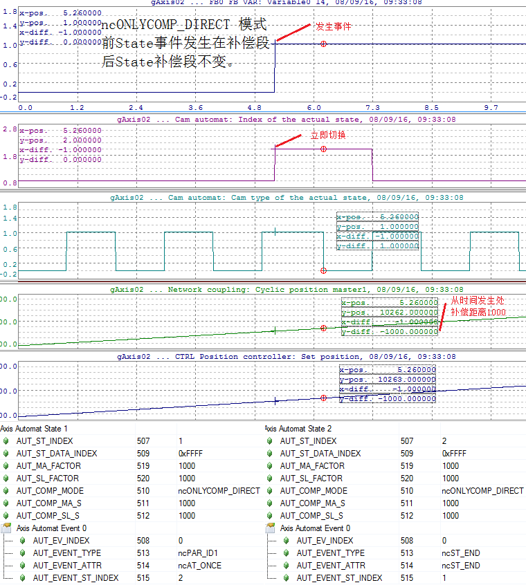
入口速比是进入点 出口速比是ID519:ID520 ID511,ID512定义的距离走。整个State主轴走ID519+ID511,从轴走ID520+ID512 此处练习补偿模式ncONLYCOMP 和ncONLYCOMP_DIRECT 区别!
|
|||||||||||||||||||||||||||||||||||
7 |
||||||||||||||||||||||||||||||||||||
|
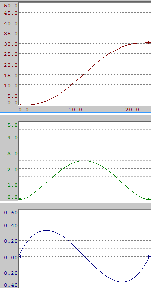
自己编辑、导入机械尺寸两种方法 5阶曲线原理 – 电子凸轮profile中使用默认5阶曲线 f(x) = a0+a1x+a2x2+a3x3+a4x4+a5x5 •f(x0) = y0 •f(x1) = y1 •f´(x0) = dy0 •f´(x1) = dy1 •f´´(x0) = ddy0 •f´´(x1) = ddy1 •保证起点和终点 位置,速度,加速度一致。 •加速度默认起点和终点为0,并保持圆滑过渡,主从轴位置设置合适会产生类似sin曲线形状. 保证起点和终点 位置,速度,加速度一致这几个条件确定函数所有参数。
•需要注意fix point的速度加速度需要输入准确否则曲线形状变形。 •边界不要弄错 •在传送profile之前,由于驱动器中没有对应这个profile的index,所以默认参数表不能使用对应index否则报错。 凸轮曲线的编辑请参考其他文档。
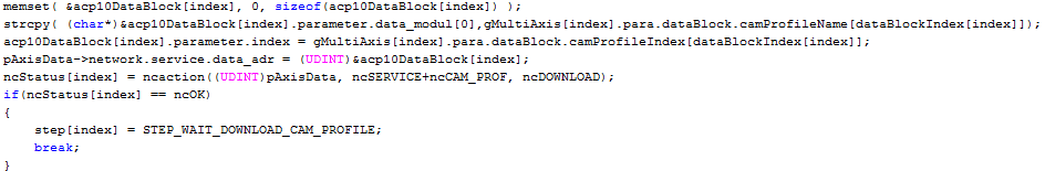
下载凸轮例子:下载时定义序号供cam使用。 case CAM_PROF_DOWNLOAD: cam_prof_download.parameter.index = 1; strcpy((char*)&cam_prof_download.parameter.data_modul[0],"acp_cam"); p_ax_dat->network.service.data_adr = (UDINT)&cam_prof_download; action_status = ncaction(ax_obj,ncSERVICE+ncCAM_PROF,ncDOWNLOAD); if ( action_status == ncOK ) { step = W_CAM_PROF_DOWNLOAD; } break; case W_CAM_PROF_DOWNLOAD: /* if ( cam_prof_download.status.data_len != 0 ) before V1.12 */ if ( cam_prof_download.status.ok == ncTRUE ) { /* Operation successfully completed */ step = <NEXT_STEP> } if ( cam_prof_download.status.error == ncTRUE ) { /* Error during operation */ step = <ERROR_STEP> } break;
|
|||||||||||||||||||||||||||||||||||
8 |
||||||||||||||||||||||||||||||||||||
|
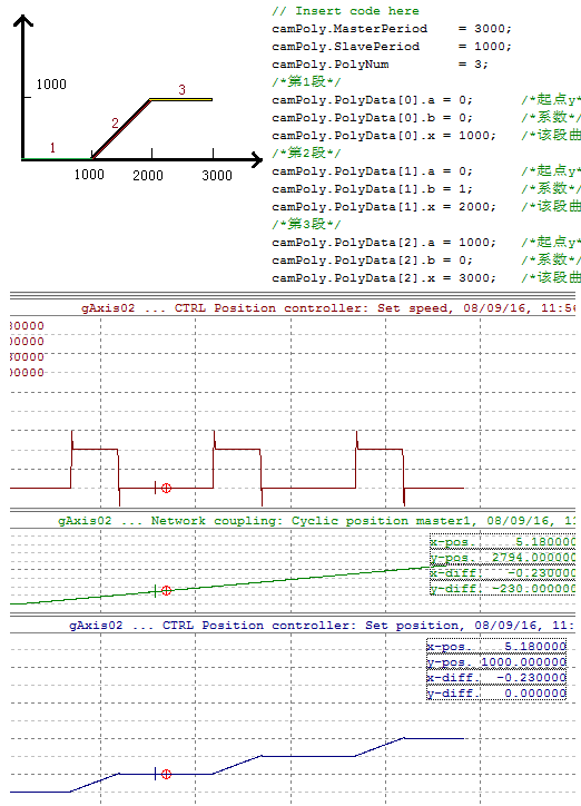
参考标准化功能块 第一段 起点Y = 0 终点X = 1000 根据 Y0= 0+b0x a=0;b=0;x0=1000(本段终点下段起点) 第二段 起点Y = 0 终点X = 2000 根据 Y1= a1+b1(x-x0) a1=0;b1=1;终点X1=2000(本段终点下段起点) 第三段 起点Y = 1000 终点X = 3000 根据 Y2= a2+b2(x-x1) a2=1000;b2=0;终点X2=3000(本段终点下段起点) 第四段 生成数据模块
传送方法和profile一样
|
|||||||||||||||||||||||||||||||||||
9 |
||||||||||||||||||||||||||||||||||||
|
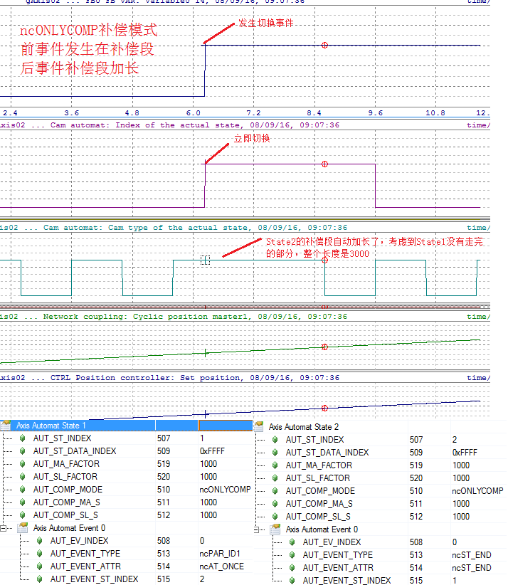
每个State在走的时候先走补偿后走同步。 ncOFF – 关闭补偿,切入这个state立即按照当前state同步段走,如果速度没有连续会发生跳变,产生振动。 ncONLYCOMP – 仅补偿 如果上一个周期正常结束的时候切入本周期,那么补偿距离和同步距离与ncONLYCOMP_DIRECT一样。如果上一个周期atOnce切入本周期,那么上一个周期没有走完的距离会考虑到本周期补偿距离中。此方式可以保证上一个周期和本周期的主从轴距离之和不变。通常我们不会这样使用。容易误解。 ncONLYCOMP_DIRECT 正常结束的时候和ncONLYCOMP一样,如果是atOnce结束,那么没走完的就不管了,立即切入当前state。 ncV_COMP_A_CYC 速度补偿 可以用于皮带补偿,动态修改ID519 AUT_MA_FACTOR,ID520 AUT_SL_FACTOR不会造成速度突变或冲击。AUT_COMP_SL_A1_MAX and AUT_COMP_SL_T_JOLT用来限定如何加减速。 其他方式没用过
|
|||||||||||||||||||||||||||||||||||
10 |
||||||||||||||||||||||||||||||||||||
|
|
|||||||||||||||||||||||||||||||||||
11 |
||||||||||||||||||||||||||||||||||||
|
先举一个例子
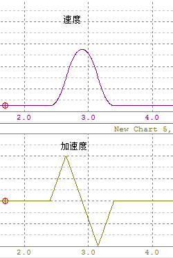
在伺服自动计算补偿距离的时候,加速度是三角形的,这和camProfile不同。
计算公式 根据入口和出口速度比例(从轴速度除以主轴速度),可以得到主轴和从轴按照以下关系的时候可以实现匀加速或匀减速。例如入口速比0,出口速比1。主轴距离1000,从轴距离500,曲线如下图。 Sslave = (Vin+Vout)/2*Smaster Vin,Vout是从轴距离除以主轴距离 程序实现 signed long MasterSCal(float vInput, float vOutput, signed long sSlave) signed long SlaveSCal(float vInput, float vOutput, signed long sMaster)
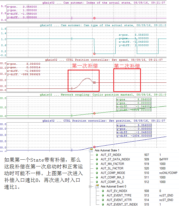
注意:如果刚启动进入补偿模式那么和其他state进入补偿速比会发生变化,曲线形状也会变化。
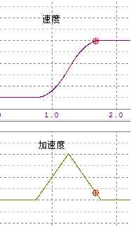
如果主轴距离设置比较长,例如入口速比1,出口速比0。主轴距离2000,从轴距离500,从轴运动加速度变大,曲线和上图相似。主轴在1000unit从轴走完,剩余部分静止。
如果继续修改从轴位置为100
可以看到加速度变大很多。 结论:减少从轴距离,从轴加速度变大。 加大主轴距离会怎么样?
结论:加大主轴距离,从轴没有变化。
加大从轴距离------加速度变的奇怪了。
此时如果限制加速度会怎么样? 此时如果修改允许反向速度会怎么样?
加大主轴距离会怎么样?时间变长了 下个测试如果加大从轴距离会怎么样?
|
|||||||||||||||||||||||||||||||||||
12 |
||||||||||||||||||||||||||||||||||||
|
提示:从轴补偿距离可以为负值 |
|||||||||||||||||||||||||||||||||||
|
如何实现?
方式1: 增加一个state
方式2: 减少从轴补偿速度最小值 到 例如 -1 问题这个参数是不是每一个state一个,还是所有state共用 ? |
|||||||||||||||||||||||||||||||||||
13 |
||||||||||||||||||||||||||||||||||||
|
在automat激活时修改参数,会在运行过程中重新计算曲线形状,需要下载cam曲线并且更新旧的曲线。对于正在运行的automat来说,有数据一致性,automat同步性要求: ▪数据一致性:参数或曲线下载过程中,automat继续以旧的参数或曲线运行,所有新的参数或曲线是同时被接受的。 ▪automat同步性:只有在指定的状态跳转发生时,新的参数或曲线才被接受。
上述要求可以通过使用两个ParID来实现: ▪AUT_ONL_PAR_LOCK(ParID:527):用于开启新参数接受锁定; ▪AUT_EVENT_ACTION(ParID:528):用于对Events设置automat同步性动作;
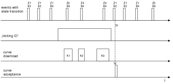
使用方法如下: 1. AUT_ONL_PAR_LOCK = 0 。允许在线修改的参数,新的参数或曲线下载后,下个状态跳转(包括一个状态内重复跳转)后新参数即生效。如果需要多次下载,则每下载一次,数据就会更新一次,这种方法不能保证参数更新时的数据一致性和automat同步性。 2. AUT_ONL_PAR_LOCK = 1。在新的参数或曲线下载前,先设定AUT_ONL_PAR_LOCK = 1,然后执行下载新的曲线和参数,完成后再设定AUT_ONL_PAR_LOCK = 0。然后新的曲线和参数在下个状态跳转(包括一个状态内重复跳转)后生效。这种方法能保证参数更新时的数据一致性,但不能保证automat同步性。
时序图如下图:K1、K2、K3在“Lockiong ID = 1”时执行下载,在“locking ID”下降沿后的第一个状态跳转(t3时刻)新曲线生效。
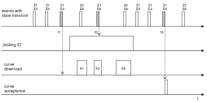
3. AUT_ONL_PAR_LOCK = 2。使用该方法时,需要设置一个标志性事件。该标志性事件需要在离线时设置(如状态1的Event 0): AUT_ST_INDEX = 1 AUT_EV_INDEX = 0 AUT_EVENT_ACTION = 0x01 在新的参数或曲线下载前,先设定AUT_ONL_PAR_LOCK = 2,然后执行下载新的曲线和参数,完成后再设定AUT_ONL_PAR_LOCK = 0。然后新的曲线和参数在标志性事件的状态跳转(包括一个状态内重复跳转)后生效。这种方法能保证参数更新时的数据一致性和automat同步性。
时序图如下图:K1、K2、K3在“Lockiong ID = 2”时执行下载,在“locking ID”下降沿后的第一个标志性事件的状态跳转(t3时刻)后新曲线生效。
|
|||||||||||||||||||||||||||||||||||
14 |
||||||||||||||||||||||||||||||||||||
|
进入电子齿轮跟随状态的轴,如果由于外部原因,需要执行正反向或停止命令。(可能是客户手动操作,或者由于报警)这时电子齿轮跟随状态被破坏了,这时我们可以通过cam restart的方式恢复原样,在包装领域就不会造成浪费。 相关参数说明: (1)ID900 ACP10PAR_AUT_STATUS:电子齿轮状态。在执行cam_start命令后,该数值变为3(active),在此期间如果执行pos,neg,stop,abs,rel等基本运动命令,从轴会退出电子齿轮状态,此时该数值变为1(standby)进入等待状态。 (2)ID771 ACP10PAR_AUT_S_SET:从轴应该到达的位置。一旦发送cam_start命令,这个数值就在计算,如果从轴执行了基本运动命令,那么从轴设定位置转换为自己的位置发生器,但是这个数值依然在计算,所以如果想恢复当前状态,只需要将从轴运动到这个位置然后执行cam_restart命令。 操作步骤: 1- 由于外部原因破坏了电子齿轮跟随状态 2- 停止主轴 3- 将从轴移动到ID771 ACP10PAR_AUT_S_SET 4- 给从轴发送cam restart命令 ID 502 设定为 273(RESTART) 注意: •发送Restart命令后将会在当前状态下继续跟随,不会从state0开始。 •从轴电子齿轮状态如果变为0,则不可以发送cam restart命令,会产生报警。只能发送cam start命令
|
|||||||||||||||||||||||||||||||||||
15 |
||||||||||||||||||||||||||||||||||||
|
反向事件限制比较多,使用时需要注意。 没有反向事件时,如果主轴反向走,那么从轴会在当前state走到边界后停止。(默认情况) 使用反向事件类型ncST_END+ncNEGATIVE时,带有补偿的state会报错。(已测试) |
|||||||||||||||||||||||||||||||||||
16 |
||||||||||||||||||||||||||||||||||||
|
Comp limit
这个参数用来限制补偿段速度,请注意他的单位。他和
参数单位是一致的,AUT_MA_V_MAX默认为1,所以AUT_COMP_SL_V_MIN通常也是+-1之间,可不要设定成1000,1000。 Cam Limit 整个运动limit |
|||||||||||||||||||||||||||||||||||
17 |
||||||||||||||||||||||||||||||||||||
|
|
|||||||||||||||||||||||||||||||||||