目录
•0. 基本信息
•1. LATCH - Event Triggered Storage
•2. LATCH功能块相关的参数ID
•2.1 LATCH_MODE
•2.2 LATCH_IN_PARID
•2.3 LATCH_EV_PARID
•2.4 LATCH_EV_TYPE
•2.5 LATCH_EV_WIDTH_MIN
•2.6 LATCH_EV_WIDTH_MAX
•2.7 Shifting the Window Position
•2.9 Online Changes to Parameters
•2.10 Limitations
•3. Example例子
•4.1 操作流程
•4.2 调试彩膜的流程
•4.3 同步关系图
•4.4 Latch功能块配置和使用
•4.5 以下分别介绍常有的两种彩膜的参数设置
编写人 |
林繁伟 |
审核人 |
(检查,测试,注释) |
|
应用归属 |
运动控制 |
|||
软件信息 |
|
硬件信息 |
||
其他 |
|
|||
版本信息 |
修改内容 |
修改人 |
||
V1.00 |
2011.02.15 创建 |
林繁伟 |
||
|
|
|
||
1. LATCH - Event Triggered Storage
LATCH – 事件触发锁存
The value of a changing input value, is to be saved (i.e. "latched") when certain trigger events occur. The trigger signal must fulfill certain conditions - such as: reaching a trigger edge within a certain window and with a certain signal width.
当设定的触发事件发生后,改变的输入值就会被保存住(类似于锁存)。触发信号必须满足设定的条件,例如在设定的窗口和设定的信号宽度内到达了触发的边沿。
In most cases, the input value is a position value, with a corresponding position sensor as trigger event. Therefore, the latch function block can be used for trigger positioning, length measurement and for print mark evaluation/control.
在大多数应用中,输入值是一个位置值;在相应位置的传感器就是产生一个触发的事件。因此这LATCH功能块就能够用于触发位置、长度测量和印刷标记的评估或者控制。
Parameter ID name |
Abrv |
Access |
Dat typ |
Value range |
Init |
Unit |
Description |
LATCH_MODE |
m |
RD,WR |
UI2 |
0,1,2,4 |
0 |
Function mode and activation |
|
+16,+32,+64 |
|||||||
LATCH_IN_PARID |
*x |
RD,WR |
UI2 |
<ParID>, 0 |
0 |
Parameter ID input value which is latched |
|
(Pointer on input value, integer data type) |
|||||||
LATCH_EV_PARID |
*e |
RD,WR |
UI2 |
<ParID>, 0 |
0 |
Parameter ID input trigger event |
|
(Pointer on trigger event input value, integer data type) |
|||||||
LATCH_EV_TYPE |
RD,WR |
UI1 |
0,1,2,3,4,5 |
0 |
Trigger event type positive/negative edge, with/without evaluation of the signal width |
||
LATCH_EV_WIDTH_MIN |
smin |
RD,WR |
I4 |
>= 0 |
0 |
of x |
Minimum signal width trigger event |
LATCH_EV_WIDTH_MAX |
smax |
RD,WR |
I4 |
>= 0 |
0 |
of x |
Maximum signal width trigger event |
LATCH_WINDOW1 |
w1 |
RD,WR |
I4 |
>= 0 |
0 |
of x |
Latch window1, valid range (p-w1) |
LATCH_WINDOW2 |
w2 |
RD,WR |
I4 |
>= 0 |
0 |
of x |
Latch window2, valid range (p+w) and for shifting the window position |
LATCH_WINDOW_POS |
p |
RD,WR |
I4 |
0 |
of x |
Window position, expected trigger position |
|
LATCH_POS_IV |
iv |
RD,WR |
I4 |
>= 0 |
0 |
of x |
Interval for shifting the window position |
LATCH_POS_IV_ELONG |
ivl |
RD,WR |
I4 |
0 |
of x |
Interval extension for shifting with trigger |
|
LATCH_T_DELAY |
td |
RD,WR |
I4 |
0 |
ms |
Delay (trigger event and input value) for compensation |
|
LATCH_EV_WIDTH |
de |
RD |
I4 |
0 |
of x |
Trigger event signal width |
|
LATCH_VALUE |
y |
RD,WR |
I4 |
0 |
of x |
Latch result value (output) |
|
LATCH_DELTA_IV |
div |
RD |
I4 |
0 |
of x |
Deviation: window position minus the result value |
|
LATCH_STATUS |
st |
RD |
UI1 |
0,1 |
0 |
Status latched to 1 for one cycle |
|
LATCH_STATUS_COUNT |
cnt |
RD,WR |
UI1 |
0 |
Status counter, value latched |
||
LATCH_ERROR_COUNT |
err |
RD,WR |
UI1 |
0 |
Error counter |
||
功能使能和模式
Mode 0 : Disable
模式 0 :功能块不使能,当前结果值会保持。
The function block can be disabled using m=0. The current result values are then "frozen".
Mode 1, 2, +16, +32 +64:Enable
模式1, 2, +16, +32 +64 :功能块使能。
The latch function stays continuously active. After reaching a valid trigger event, the input value is latched. Additionally the status counter is incremented and the latch status is set to 1 for only one cycle (400us). The latch status then returns to 0 ("status pulse"). The status counter is preset to 0 when the FB is enabled. However, it can also be reset during operation. This status outputs can be used for diagnostics (TRACE) or to control function blocks (EVWR).
LATCH锁存功能保持连续激活。当一个有效触发事件到达时候,输入的信号值就被锁存住。同时状态计数器就会累加,锁存状态会在伺服的一个扫描周期(400us)内置一,然后返回到0(就像是状态脉冲)。当功能块使能的瞬间,状态计数器会预设置为0。然而状态计数器还是能够在功能块激活中复位或者设置其他值。状态输出能够用于诊断(例如TRACE)或者用于控制功能块(例如EVWR)
The method of operation is setup differently using the function mode: The check of the window range and the way shifting a window position (1,2,4), the reaction on exceeding the window range if no valid trigger occurs (+16, +32), the initialization of the first window position (+64 -> 1. expected value).
使用不同的功能模式来设定不同操作的方法:窗口范围的检测、 窗口位置的偏移方式(模式1、2、4)、如果没有有效的触发发生时在超过窗口范围的反应(+16模式,+32模式)、第一次窗口位置即期望触发位置的初始值(+64模式是把第一次触发值作为第一次的期望触发位置值)
Mode |
shift the window position starting from |
without trigger replace latch value by |
latch status/count without trigger |
1. window position |
模式 |
窗口位置偏置开始点 |
当没有触发时候的 代替锁存值 |
当没有触发时候的 锁存状态/计数器值 |
第一次窗口位置 即期望触发位置的初始值 |
1=1 |
latch value |
window position |
yes |
LATCH_WINDOW_POS |
(0000001b) |
锁存结果值 |
期望触发位置值 即窗口值 |
是 |
设定的期望触发位置 初始值为0 |
2=2 |
window position |
window position |
yes |
LATCH_WINDOW_POS |
(0000001b) |
期望触发位置值 即窗口值 |
期望触发位置值 即窗口值 |
是 |
设定的期望触发位置 初始值为0 |
4=4 |
no window shift |
all triggers valid |
all triggers valid |
LATCH_WINDOW_POS |
(0000100 b) |
没有窗口检测范围 且窗口不偏置 |
所有的触发都有效 |
所有的触发都有效 |
设定的期望触发位置 初始值为0 |
17=1+16 |
latch value |
old latch value remains |
yes |
LATCH_WINDOW_POS |
(0010001 b) |
锁存结果值 |
保留旧的锁存值 |
是 |
设定的期望触发位置 初始值为0 |
18=2+16 |
window position |
old latch value remains |
yes |
LATCH_WINDOW_POS |
(0010010 b) |
期望触发位置值 即窗口值 |
保留旧的锁存值 |
是 |
设定的期望触发位置 初始值为0 |
33=1+32 |
latch value |
window position |
no |
LATCH_WINDOW_POS |
(0100001 b) |
锁存结果值 |
期望触发位置值 即窗口值 |
否 |
设定的期望触发位置 初始值为0 |
34=2+32 |
window position |
window position |
no |
LATCH_WINDOW_POS |
(0100010 b) |
期望触发位置值 即窗口值 |
期望触发位置值 即窗口值 |
否 |
设定的期望触发位置 初始值为0 |
49=1+16+32 |
latch value |
old latch value remains |
no |
LATCH_WINDOW_POS |
(0110001 b) |
锁存结果值 |
保留旧的锁存值 |
否 |
设定的期望触发位置 初始值为0 |
50=2+16+32 |
window position |
old latch value remains |
no |
LATCH_WINDOW_POS |
(0110010 b) |
期望触发位置值 即窗口值 |
保留旧的锁存值 |
否 |
设定的期望触发位置 初始值为0 |
65=1+64 |
latch value |
window position |
yes |
latch value of 1. trigger |
(1000001 b) |
锁存结果值 |
期望触发位置值 即窗口值 |
是 |
把第一次触发值作为 第一次的期望触发位置值 |
66=2+64 |
window position |
window position |
yes |
latch value of 1. trigger |
(1000010 b) |
期望触发位置值 即窗口值 |
期望触发位置值 即窗口值 |
是 |
把第一次触发值作为 第一次的期望触发位置值 |
81=1+16+64 |
latch value |
old latch value remains |
yes |
latch value of 1. trigger |
(1010001 b) |
锁存结果值 |
保留旧的锁存值 |
是 |
把第一次触发值作为 第一次的期望触发位置值 |
82=2+16+64 |
window position |
old latch value remains |
yes |
latch value of 1. trigger |
(1010010 b) |
期望触发位置值 即窗口值 |
保留旧的锁存值 |
是 |
把第一次触发值作为 第一次的期望触发位置值 |
97=1+32+64 |
latch value |
window position |
no |
latch value of 1. trigger |
(1100001 b) |
锁存结果值 |
期望触发位置值 即窗口值 |
否 |
把第一次触发值作为 第一次的期望触发位置值 |
98=2+32+64 |
window position |
window position |
no |
latch value of 1. trigger |
(1100010 b) |
期望触发位置值 即窗口值 |
期望触发位置值 即窗口值 |
否 |
把第一次触发值作为 第一次的期望触发位置值 |
113=1+16+32+64 |
latch value |
old latch value remains |
no |
latch value of 1. trigger |
(1110001 b) |
锁存结果值 |
保留旧的锁存值 |
否 |
把第一次触发值作为 第一次的期望触发位置值 |
114=2+16+32+64 |
window position |
old latch value remains |
no |
latch value of 1. trigger |
(1110010 b) |
期望触发位置值 即窗口值 |
保留旧的锁存值 |
否 |
把第一次触发值作为 第一次的期望触发位置值 |
锁存的输入变量的参数号(输入值的指针,整型的数据类型)
Parameter ID input value which is latched(Pointer on input value, integer data type)
触发输入事件的参数号(触发输入事件的指针,整型的数据类型)
Parameter ID input trigger event(Pointer on trigger event input value, integer data type)
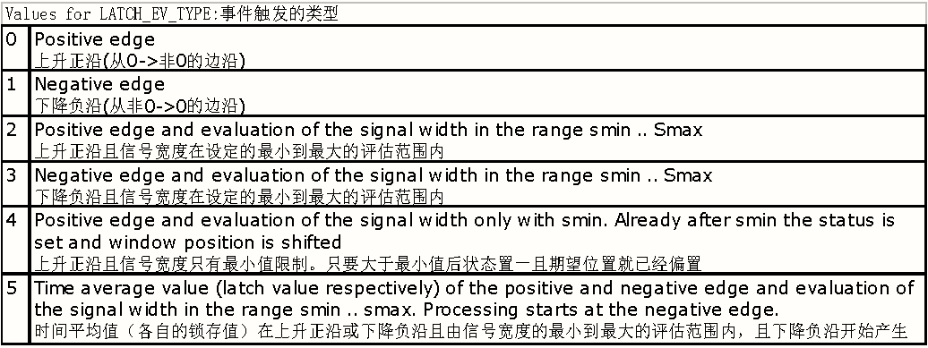
触发事件的类型:上升沿/下降沿,有/没有信号宽度的评估
Trigger event type positive/negative edge, with/without evaluation of the signal width
触发事件的最小信号宽度(以输入信号为参考)
Minimum signal width trigger event
触发事件的最大信号宽度(以输入信号为参考)
Maximum signal width trigger event
The trigger event is determined using two parameter IDs: LATCH_EV_PARID defines the input for the event value (event source). LATCH_EV_TYPE defines how the event signal is evaluated; i.e. positive or negative edge, with or without evaluation of the signal width. The event value is a logical value - i.e. only value changes from 0 to not equal to 0 (positive edge) and from not equal to 0 to 0 (negative edge) are recognized. "Any" value can be evaluated by connecting a CMP function block in series.
触发事件是由2个参数号来决定:LATCH_EV_PARID定义了事件值的输入(事件的来源),LATCH_EV_TYPE定义了事件信号是怎样产生的。换言之上升沿/下降沿,有/没有信号宽度的评估。事件值是一个逻辑值:换言之事件值只有从0到不等于0(上升沿)和从不等于0到0(下降沿)的时候被识别。一些值是能够通过连接到CMP功能块来产生。
A few examples of trigger event parameter IDs, a HW supported latch function reduces the velocity dependent error of the input value:
以下是一些触发参数ID号的例子,硬件支持锁存功能减少由锁存输入值的速度引起的偏差。
STAT_TRIGGER1: X1端子的Trigger1 |
Status change on the Trigger1 digital input |
(Terminal connection 1 connector X1 or Force Function) |
|
STAT_TRIGGER2: X1端子的Trigger2 |
Status change on the Trigger2 digital input |
(Terminal connection 2 connector X1 or Force Function) |
|
STAT_POS_LIMIT_SWITCH: X1端子的硬件正限位 |
Status change on the positive hardware end switch |
(Terminal connection 5 connector X1 or Force Function) |
|
STAT_NEG_LIMIT_SWITCH: X1端子的硬件负限位 |
Status change on the negative hardware end switch |
(Terminal connection 6 connector X1 or Force Function) |
|
STAT_REFERENCE_SWITCH: X1端子的参考点 |
Status change on the reference switch digital input |
(Terminal connection 7 connector X1 or Force Function) |
|
ENCOD_REF_PULSE_STATUS: 编码器1的零位参考点脉冲 |
Encoder1 reference pulse status change |
The combination with the input parameter ID ENCOD1_S_ACT and positive edge minimizes the velocity dependent error. |
|
ENCOD2_REF_PULSE_STATUS: 编码器2的零位参考点脉冲 |
Encoder2 reference pulse status change |
The combination with the input parameter ID ENCOD2_S_ACT and positive edge minimizes the velocity dependent error. |
|
ENCOD3_REF_PULSE_STATUS: 编码器2的零位参考点脉冲 |
Encoder3 reference pulse status change |
The combination with the input parameter ID ENCOD3_S_ACT and positive edge minimizes the velocity dependent error. |
|
AIO_CMP1_VALUE+Slot: 模拟量通道1比较输出值 |
Channel1 comparator output. |
AIO_CMP2_VALUE+Slot: 模拟量通道2比较输出值 |
Channel2 comparator output. |
Comparator output signal of the AIO-FB on use of a AC132 module in the card slot 2..4. |
|
DIO_IN7+1:数字量输入点 |
Digital trigger inputs on a BAC0130. Only for the 2nd ACOPOSmulti axis. |
DIO_IN8+1:数字量输入点 |
|
Evaluation of the Trigger Event Signal Width
触发事件信号宽度的评估
A valid range is set for the signal width of a trigger event for event types 2, 3 and 5, using the values smin and smax. The width applies to the input value x, between the pos. and neg. signal edges.
The subsequent window check then only receives the latch value of a signal determined as being "valid".
在触发事件信号宽度的事件类型2、3和5的时候使用smin 和 smax这2个参数设置值来设定一个有效的范围。在上升正沿和下降负沿的两个信号边沿之间的宽度是以输入值x作为参考。后来的窗口检测是在只接收到信号检测锁存值的时候作为有效的。
This signal preprocessing, together with the window check, allows a simple method for recognizing marks and patterns ("selection of reference data").
信号的预处理是同时包括窗口检测,采用一个简单的方法来识别色标和图案(参考数据的选择)
The signal width de, determined at each neg. edge, is available as parameter ID for diagnostic purposes (TRACE).
在每个下降负沿的时候检测的信号宽度de,、作为诊断目的(TRACE)的参数ID号是有效。
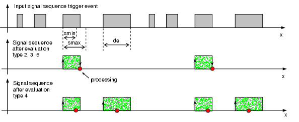
When using type 2 and 5 (pos. edge and average value), take into account that delayed processing results, which depends on the signal width and the speed dx/dt! In extreme cases, (at x-standstill on the high level), the pos. edge is reached, however the neg. edge is not. As a result, the evaluation of the signal width is not completed.
当使用类型2和5(上升正沿和平均值)的时候,必须考虑到过程结果是延迟后的,它是依赖于信号宽度和速度dx/dt。在极端的情况下,在高电平时候输入值x停止则上升正沿已经到达,然而下降负沿还没有到达。结果信号宽度的评估还没完成。
Using event type 4 reduces this delay. At the pos. edge the latch value is sampled and further processing (status and window handling) starts already after exceeding smin. Disadvantage of type 4: There is no examination for smax.
使用类型4能够减少延迟。锁存值在上升正沿就已经采样同时更多的过程(状态和窗口的处理)在超过smin的时候就已经在开始了。类型4的缺点是没有smax的检测。
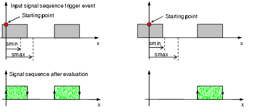
Behavior of event type 2, 3, 4 and 5 when activated on the high level:
事件类型2、3、4和5在已经激活在高电平时候的反应
If the latch FB is activated on the high level of the trigger signal, the rest of the signal width is evaluated from the starting point. This guarantees that the first trigger event is also not "lost", when it is aligned to the front edge at the beginning.
如果Latch功能块是在触发信号的高电平的时候被激活,信号宽度的剩余部分是从启动点开始评估。当它排列在起点的时候的前面的边沿,这样可以保证第一次触发事件也是没有丢失的。
However, errors occur in the latch value, depending on the current starting point and at a start speed unequal to 0. There is also the possibility for error that a signal which is too wide is accepted as "valid".
然而依赖于当前启动点和在不等于0的启动速度的锁存值就可能发生错误。因为当时信号宽度很宽的话就认为是有效的,这也有可能引起错误的可能性。
2.7 Shifting the Window Position
窗口位置的偏置
The window position and the windows define a valid range for the occurrence of a trigger event, with respect to the input value x. As a result, the window position can be seen as the expected value (set value) and the windows can be seen as the asymmetrical tolerance range.
为了触发事件的发生且顾及输入值x,窗口位置和窗口定义一个有效的范围。结果窗口位置可以看作为一个期望值(设定值)和窗口可以看作为不对称的公差范围。
Mode 1: Cyclic window shift starting from the latch value
模式1:从锁存值开始周期性的窗口偏置
In mode 1, the window position is automatically shifted as follows:
模式1下,窗口位置是按照以下规律自动偏置:
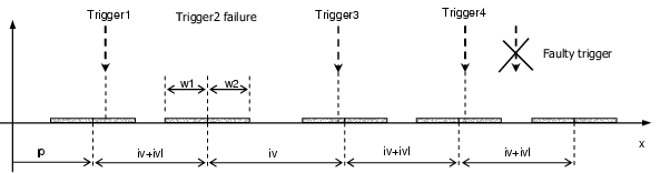
1. If the trigger occurs within the current window range , the shift takes place starting from the current latch value, with the interval (iv+ivl).
1、如果触发发生在当前的窗口范围内,就是从当前锁存值以设定的间隔(iv+ivl)开始偏置。
2. If no trigger occurs, the calculation continues from the current window position (expected value), with the interval iv. In this case, the old window position is entered as "replacement latch value" and the deviation div is set to 0. "No trigger" is detected when the value of window position plus window2 has been exceeded (x > p+w2). If the window is set too large, delays occur when shifting without trigger and the possibility for a faulty trigger is increased. Setting a window too small means that any "good" triggers will be missed, and that a synchronization after an interval change will take longer.
2、如果没有触发发生,就从当前的窗口位置(期望值)以设定的间隔(iv)开始延长计算。在这种情况下,前一个旧的窗口位置是以替换锁存值来加入,同时偏差值div设置为0。当超过窗口位置加上窗口2(x > p+w2)还没检测到就认为是没有触发。如果窗口设定得太大,当没有触发的偏置滞后发生和增加错误触发的可能性。窗口设定得太小就意味着一些正确的触发可能会错失,且在间隔改变后需要更长的同步时间。
In both cases, status (for one scan cycle) and status counter are set. In the second case however, the error counter is additionally increased. This counter is preset to 0 when the FB is enabled. However, it can also be reset during operation. The counter value serves as diagnostics indicator and as abort criteria.
Properly selecting the interval extension ivl (or reduction e.g.: ivl = -iv/4) allows a synchronization after an interval change. For example, such a "jump" in the trigger interval occurs after a change in the product length or at bonding sections on a carrier tape.
在以上2种情况下,状态(只有一个伺服扫描周期0.4ms的高电平)和状态计数器会置一。然而在第2种情况下,错误计数器会累积加一。当功能块使能的瞬间,计数器会预设置为0。然而它也是能够在运行过程中复位。这个计数器的值可以作为诊断只是和终止流程来应用。间隔延长ivl(或减少例如ivl = -iv/4)的正确选择允许在间隔改变后的同步。例如,当产品长度发生改变后或者传送带的搭接段的时候,这种跳变在触发间隔内发生。
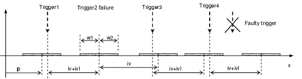
在使能功能块之前设置好期望位置p,
第一次在期望位置的窗口范围内触发,则下一次的期望位置就是第一次触发的位置再加上设定的间隔(iv+ivl)开始偏置。
第二次在设定的窗口范围内触发失败,则下一次的期望位置就是从第二次的期望位置再加上设定的间隔(iv)开始偏置。
第三次在设定的窗口范围内触发正常,则下一次的期望位置就是第三次触发的位置再加上设定的间隔(iv+ivl)开始偏置。第四次在设定的窗口范围内触发正常,则下一次的期望位置就是第四次触发的位置再加上设定的间隔(iv+ivl)开始偏置。当在设定的窗口范围外有触发信号,那些触发会认为是无效的,会被忽略(能够用于提高抗干扰能力)。
Mode 2: Cyclic window shift starting from the window position
模式2:从窗口位置开始周期性的窗口偏置
The functional behavior is generally the same as in mode1, other than the following differences:
If the trigger occurs within the current window, the shift takes place starting from the current window position (expected value), with the interval (iv+ivl). Therefore, the shift in this mode always starts from the expected value. As a result, the interval tracking must take place "externally" or a fixed interval has to be used.
这种功能特性和模式一的通用特性相同,只是有以下的差异:
如果触发发生在当前窗口范围内,从当前窗口位置值(期望值)以设定的间隔(iv+ivl)开始偏置。因此这种模式总是从期望值开始偏置。结果间隔追踪必须以表面上的间隔或者使用确定的间隔来替换
在使能功能块之前设置好期望位置p,
第一次在期望位置的窗口范围内触发,则下一次的期望位置就是从本次期望位置再加上设定的间隔(iv+ivl)开始偏置。
第二次在设定的窗口范围内触发失败,则下一次的期望位置就是从本次期望位置再加上设定的间隔(iv)开始偏置。
第三次在设定的窗口范围内触发正常,则下一次的期望位置就是从本次期望位置再加上设定的间隔(iv+ivl)开始偏置。
第四次在设定的窗口范围内触发正常,则下一次的期望位置就是从本次期望位置再加上设定的间隔(iv+ivl)开始偏置。
当在设定的窗口范围外有触发信号,那些触发会认为是无效的,会被忽略(能够用于提高抗干扰能力)。
Mode 4: No window check and no window shift
模式4:没有窗口检测范围且窗口不偏置
This mode is designed for "non-cyclic" applications or for operation without interval. The window check is disabled - all triggers are accepted. The window position is not automatically shifted. Parameter iv, ivl, w1, w2 have no effect.
这种模式是为了没有周期性的应用或为了没有间隔距离的操作而设计的。窗口检测已经被禁止-所有触发都是允许的。窗口位置不是自动偏置的。参数iv, ivl, w1, w2都不起作用。
滞后的补偿
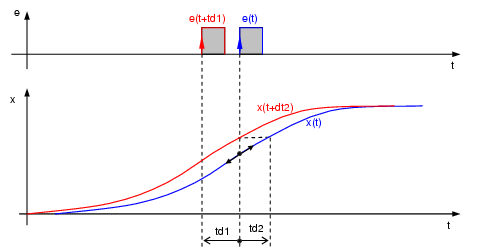
Delays and dead times cause a speed-dependent offset in the latch value. For certain cases, a compensation can be achieved using the parameter LATCH_T_DELAY.
If the delay spans most of the trigger event, compensation takes place with negative values - otherwise positive values are used when the delay spans most of the input signal (dt = dt2 - dt1).
在锁存值里,滞后和死区时间引起依赖速度的偏置。在某些应用中,能够使用参数LATCH_T_DELAY来实现补偿。如果大多数的触发事件在滞后的时间内,就是负值的补偿,否则正值的补偿是用于当大多数的输入信号(dt = dt2 - dt1)在滞后的时间内。
Compensation is performed using linear interpolation or extrapolation. As a result, exact compensation only occurs when there is a constant x(t) increase and when short delays occur.
补偿是使用线性插补或者预测推断来完成的。结果精确的补偿只发生在当存在常数x(t)增加和很少的滞后发生。
2.9 Online Changes to Parameters
在线修改的参数
The following parameters cannot be changed when the function block is enabled (m != 0):
当功能块已经使能(m != 0)之后,以下参数是不能改变的:
LATCH_MODE, LATCH_IN_PARID, LATCH_EV_PARID
All other parameters can also be set during operation. As a result, online settings are possible at start-up and applications can be implemented which require tracking (control) of parameters. When making an online change to the window position LATCH_WINDOW_POS, make sure that this value is also continually shifted by the FB (i.e. both the input parameter and the result value).
其他所有的参数能够在运行过程中设置。结果,当需要控制参数的时候,在线修改的参数允许在启动时候和应用过程中来执行。当在线改变LATCH_WINDOW_POS窗口位置值的时候,必须清楚知道这个值也是由FB功能块连续偏置的(例如输入参数和结果值这两个值)
限制因素
Only integer values are allowed as trigger event (no float values). In addition, only logical changes TRUE (!= 0) and FALSE (=0) are recognized. Therefore, not all event levels are supported. These two limitations can be avoided by connecting a comparator FB in series.
只允许整型变量值作为触发事件(不允许浮点型变量值)。另外,只有当逻辑改变TRUE (!= 0) 和 FALSE (=0) 的时候能够识别。因此不是所有的事件等级类型都支持。这2条限制能够通过连接到一系列的比较功能块来避免。
Only integer values are allowed as input value. For example, float values can be modified with the ARITH FB. As a result, the value range is expanded by multiplying with a corresponding scaling factor. Therefore, make sure that a potential INT32 overflow does not occur when shifting the window.
只允许整型变量值作为输入值。例如浮点型变量值能够通过运算ARITH功能块来修改。因此这值的范围通过相应量程比例乘法来扩展。所以当窗口位置值偏置的时候,确信INT32位溢出的可能性没有发生。
The evaluation of the signal width and the cyclic window shift only functions for increasing input values (pos. direction of movement).
信号宽度的评估和窗口周期性的偏置只对增加的输入值起作用(运动的正方向)。
The following limitations result from the scan cycle of 400 μs:
因为400us的伺服扫描周期而产生以下的限制:
A minimum duration to guarantee the recognition of a trigger signal (both high and low level) and lower limit when evaluating the signal width with smin. Speed-dependent resolution (deviations) at the result value, at the window position and at the evaluation of the signal width.
持续一个最短的时间才会识别为触发信号(高和低两个电平)和当采用smin的下限制值来评估信号宽度。在窗口位置进而在信号宽度的评估是在依赖速度的结果值的解析。
When using the two trigger event parameter IDs STAT_TRIGGER1 and STAT_TRIGGER2 a considerably higher resolution occurs at the result value and at the minimum signal width. The hardware support allows this to be achieved when the trigger edge times are determined.
当使用STAT_TRIGGER1 和 STAT_TRIGGER2这2个触发事件参数ID号相当高分辨率的发生在结果值和最小信号宽度。当触发边沿时间能够检测到时候,硬件支持允许达到目的。
A sensor on the trigger1 input detects print mark signals. The position of the carrier tape is evaluated using an external encoder position. Only one specific edge should be evaluated and the corresponding position should be determined from the cyclic pattern of the print mark signal.
一个传感器装在伺服的trigger1端子上,用于检测印刷的色标信号。传输带的位置使用一个外部编码器位置。只有一个特别的边沿能够产生,同时对应的位置能够由循环图案色标信号的检测出来。
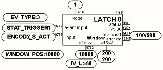
Creating, configuring and defining the connection structure of the LATCH function block No0:
创建、配置和定义LATCHFB0的关系结构:
FUNCTION_BLOCK_CREATE |
<- LATCH_MODE+0 |
Creating the LATCH FB0 创建LATCH功能块0 (每种功能块有8个:FB0~FB7) |
LATCH_IN_PARID+0 |
<- ENCOD2_S_ACT |
Link input with encoder2 position 链接到第2个编码器的位置(一般测量编码器是作为第2个) |
LATCH_EV_PARID+0 |
<- STAT_TRIGGER1 |
Link trigger event with digital input 链接到数字量触发事件(X1端子中的Trigger1) |
LATCH_EV_TYPE +0 |
<- 3 |
Negative edge and evaluation of the signal width 下降负边沿和信号宽度评估 |
LATCH_EV_WIDTH_MIN+0 |
<- 100 |
Minimum trigger signal width 100 units 最小的触发信号宽度100units |
LATCH_EV_WIDTH_MAX+0 |
<- 500 |
Maximum trigger signal width 500 units 最大的触发信号宽度500units |
LATCH_WINDOW1+0 |
<- 200 |
Latch window in neg. direction 200 units 锁存窗口的负方向200units |
LATCH_WINDOW2+0 |
<- 200 |
Latch window in pos. direction 200 units 锁存窗口的正方向200units |
LATCH_WINDOW_POS+0 |
<- 10000 |
first window position = first expected value 第一个窗口位置即第一次期望位置值 |
LATCH_POS_IV+0 |
<- 10000 |
Interval of the signal period 信号的间隔周期 |
LATCH_POS_IV_ELONG+0 |
<- -50 |
Interval reduction when a trigger occurs 当触发发生时候周期的减少 |
LATCH_T_DELAY+0 |
<- 0 |
No delay compensation 没有延时补偿 |
LATCH_MODE+0 |
<- 1 |
Enable FB 使能功能块 |
Cyclic Operation循环操作:
y |
<- LATCH_VALUE+0 |
Read result value 读取结果值(实际触发或功能块输出值) |
div |
<- LATCH_DELTA_IV +0 |
Read deviation for diagnosis 读取偏差值(用于诊断或纠偏) |
err |
<- LATCH_ERROR_COUNT+0 |
Read error counter for diagnosis 读取故障计数器(用于诊断) |
if (err) LATCH_ERROR_COUNT+0 |
<- 0 |
Reset error counter 复位故障计数器 |
白膜没有位置的限制,可以从任何一个位置开始,只要保证每次送切的膜长一致就可以。相比之下,彩膜送切的位置与膜长所要求的精度高很多。除了薄膜长度以外,送切后彩膜的图案对称度也是一个检验的标准。一般地,印制出来的彩膜都会在两段对称图案的后面留有一个空白段,是待切部分。每一个空白待切部分的薄膜边缘都会有一个黑色的一小块色标印记(PrintMark)。利用一个光电传感器可以在送膜过程中捕获这一个印记,从而让伺服控制器得到这个信息。工艺上要求,印记一旦被检测到,上膜电机会完成一段位移,然后开始切膜。如果上膜电机一直以一定的速度运动,那么,切膜电机从检测到印记与上膜电机同步到最后完成切膜应该是容易控制的。但是,上膜电机仍然需要和主电机保持同步,完成先慢后快的轨迹。当然,匀速送切彩膜方式可以用作第一次的手动校准。
上膜根据设定的上膜凸轮曲线和主轴同步。上膜在主机到达设定的相位时候切入耦合曲线,在同步上膜过程中色标传感器触发到色标时候的期望上膜位置和实际上膜位置的偏差。这得到了此次图案超前或者滞后的位置偏差量,采用虚轴作为从轴附加轴来做相对位移运行,达到修正图案位置的偏差。
1、进行手动上膜的方式来定彩膜图案位置:
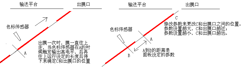
上膜寻参零位:当使用彩膜功能时候才有效,色标传感器会先定好彩膜的位置后延时半秒后再进行切膜。进行出膜一次操作时,上膜一直在转,当色标传感器检测到色标的时候输出高电平24VDC到上膜伺服驱动器的18针端子的第二个端子Trigger2后再出设定此参数(mm)的膜长才停下来。此参数影响膜上膜彩色图案和包裹物之间的相对位置。
2、按照凸轮曲线进行手动出膜一次:
3、根据定好位置的色标位置也就是知道第一次色标的位置即色标期望位置:
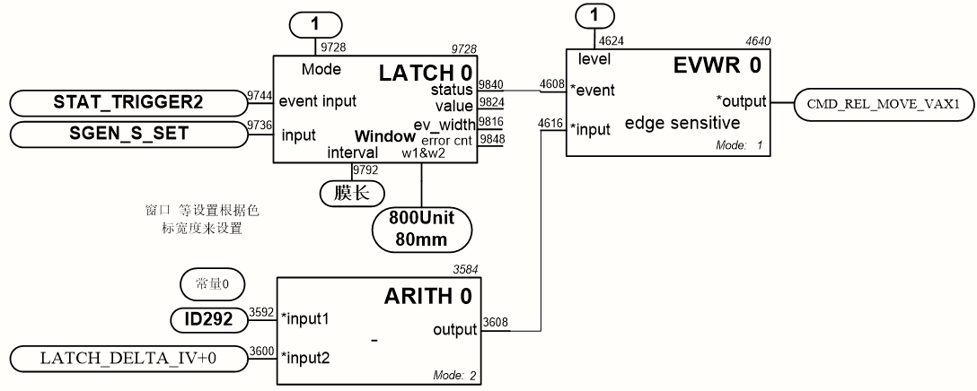
4、用LATCH功能块得到的偏差量来进行色标纠偏:
1、先关闭彩膜功能,
2、设定好上膜曲线来试包;
3、然后微调同步参数。使得连续切出来的膜的长度和实际一张完整彩膜的长度一样;
4、再来使能彩膜功能来设定彩膜参数。
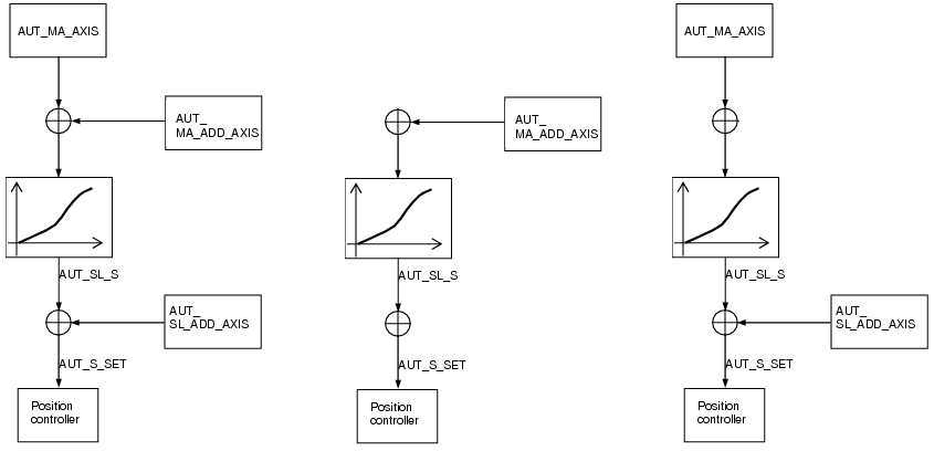
下方第一个图是主轴和附加轴的同步关系图
下方第二个图是手动出膜的同步关系图:送膜的虚轴作为主轴附加轴,屏蔽主轴和从轴附加轴
下方第三个图是自动运行中出膜的同步关系图:主机位置作为主轴,屏蔽主轴附加轴,送膜的虚轴作为从轴附加轴来进行彩膜纠偏
因为纠偏量LATCH_DELTA_IV是期望窗口位置减去实际触发结果值的偏差。对于本应用的情况需要进行负纠偏,所以需要0减去LATCH_DELTA_IV后,再赋值给CMD_REL_MOVE_VAX1。
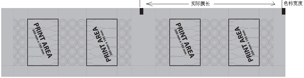
上图的彩膜的色标宽度必须大于15mm,否则在高速上膜的时候色标传感器无法响应色标。
在检测到黑色块时,色标传感器的输出必须是高电平,否则重新设定色标传感器的模式。
⊙ 色标最小宽度:至少是色标宽度的三分二。比如色标宽度是15mm。此参数设置设置为10mm。
一般此参数设置大于10mm。
⊙ 色标窗口宽度:一般是色标宽度的4倍。比如色标宽度是15mm。此参数设置设置为60mm。
一般此参数设置大于40mm。
⊙ 色标位置:此参数影响在运行中上膜纠偏的效果。S总长(膜长)减去上膜寻参零位。
比如S总长(膜长)是474mm,上膜寻参零位是280mm,即此参数设置设置为474-280=194mm。
根据连续运行中的效果来精确微调几毫米此参数。
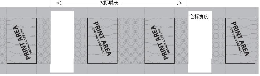
在检测到白色区域时,色标传感器的输出必须是高电平,否则重新设定色标传感器的模式。
⊙ 色标最小宽度:至少是色标宽度的三分一。比如色标宽度是80mm。此参数设置设置为26mm。
一般此参数设置为20mm。
⊙ 色标窗口宽度:一般是色标宽度的三分二。比如色标宽度是80mm。此参数设置设置为52mm。
一般此参数设置为60mm。
⊙ 色标位置:此参数影响在运行中上膜纠偏的效果。S总长(膜长)减去上膜寻参零位。
比如S总长(膜长)是474mm,上膜寻参零位是280mm,即此参数设置设置为474-280=194mm。
根据连续运行中的效果来精确微调几毫米此参数。
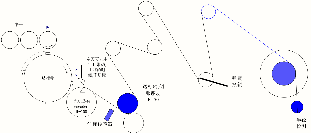
送标轴与作为主轴的刀辊的编码器同步运行。主从同步关系为360:标长,即刀辊转1圈时候,送一张标。
Latch的模式66,色标传感器第一次触发得到的主轴位置作为第一次期望位置,同时加上标长即得到第二次期望触发位置。当第二次触发时候得到测量主轴编码器即刀辊的位置和期望的位置的偏差值。通过主从同步关系为360:标长,可以推算出系统唯一能控制的送标的调整量,送多或者送少相应的标长,来控制每次切在标上固定的位置。
由于送标轴需要在固定的相位来切出耦合,所以只能采用从轴附加轴来进行纠偏。
