1. 基本信息
编写人 |
林繁伟 |
审核人 |
(检查,测试,注释) |
|
应用归属 |
运动控制 |
|||
软件信息 |
|
硬件信息 |
||
其他 |
|
|||
版本信息 |
修改内容 |
修改人 |
||
V1.00 |
创建 |
林繁伟 |
||
|
|
|
||
2. 硬件拓扑
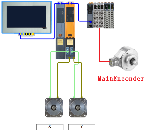
主轴测量编码器是P+F:TVI40N-14TK0T6TN-01000 ,分辨率是1000 INC/Rev
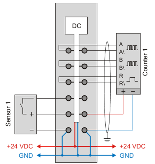
X20DC1196:X20 digital counter module, 1 ABR incremental encoders, 5 V, 600 kHz input frequency,4x evaluation
3. Coupling to data points
3.1被动电源模块参数表需要配置的参数
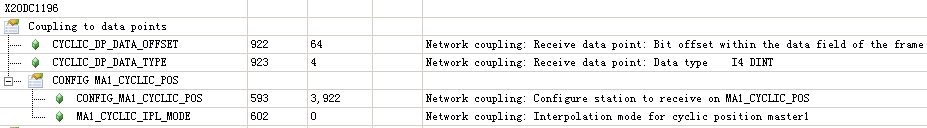
3.2参数CYCLIC_DP_DATA_OFFSETID922的获取
记下模块的路径IF1.ST3.IF1.ST2和DC1196的ChannelName ‘Encoder01’
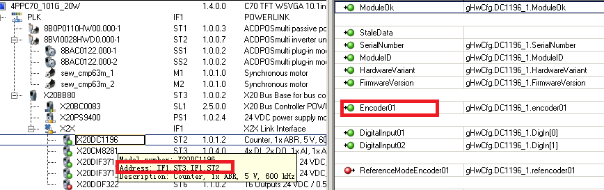
用手转动编码器1圈,在Monitor下可以看到Encoder01增加或减少4000Unit (1000*4)的话,就可以确认接线和硬件正常。
通过plAction函数获取所需要的数据在powerlink通讯中的偏移量参数ID922
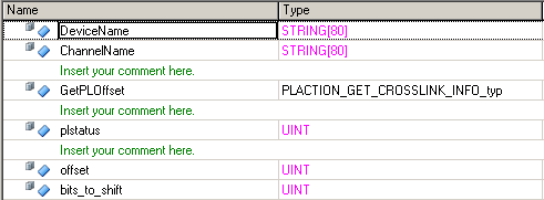
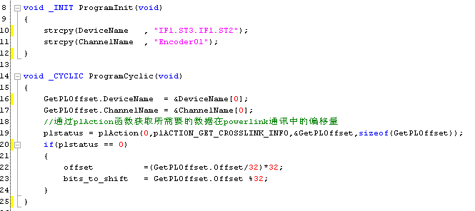
在程序里面运行一次即可得到偏移量offset即参数ID922,以后可以屏蔽或删除这程序
![]()
3.3参数CYCLIC_DP_DATA_TYPE ID923的确定
DC1196模块配置如下:是32位的计数器,
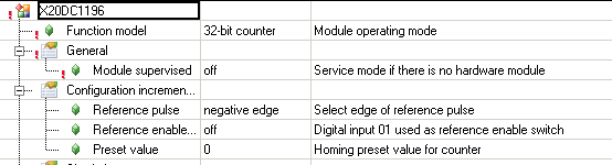
因此ID923配置为I4 (DINT)即4
Value |
Data type |
Description |
4 |
I4 |
Integer position or I4 counter or 32bit information |
5 |
UI1 |
UI1 counter or 8bit information. Only allowed with interpolation mode 0 |
6 |
UI2 |
UI2 counter or 16bit information. Only allowed with interpolation mode 0 |
7 |
UI4 |
Integer position or UI4 counter or 32bit information |
64 |
I4+R4 |
Position with integer an fractional part, like an ACOPOS to ACOPOS coupling |
65 |
I4+R4+UI4 |
Position with integer an fractional part and UI4 counter for coupling to a superimposed, slow cycle |
66 |
I4+R4+UI4 |
Position with integer an fractional part and UI4 counter for coupling to a superimposed, slow cycle. Data is generated in a task class that can be interrupted by the send procedure (jitter) |
3.4 参数CONFIG_MA1_CYCLIC_POS及其MA1_CYCLIC_IPL_MODE的配置
CONFIG_MA1_CYCLIC_POS |
node, CYCLIC_DP_DATA_OFFSET |
Configure station for receiving MA1_CYCLIC_POS |
MA1_CYCLIC_IPL_MODE |
0 |
Interpolation off |
BC0083的POWERLINK站点设定为3,所以node=3;CYCLIC_DP_DATA_OFFSET就是ID922
结果CONFIG_MA1_CYCLIC_POS = 3,922
MA1_CYCLIC_IPL_MODE:Network coupling: Interpolation mode for cyclic position master1
0: off, 1: linear, 2 and 4 quadratic
这里设置为0: off
3.5 下载程序后,Trace或读取MA1_CYCLIC_POS(ID524)来验证功能有效
转动编码器1圈,MA1_CYCLIC_POS应该增加或减少4000Unit (1000*4)的话,就一切参数配置正确。
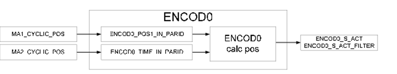
4. Virtual Encoder
4.1 Why need Virtual Encoder
可以把MA1_CYCLIC_POS(ID524)发送到网络上,让其他轴与其同步。
但是MA1_CYCLIC_POS的量程单位是1unit=1plus,而且方向也有可能是相反的,例如输送带往前运行,编码器的数值是减少的。如果不使用Virtual Encoder就需要在从轴的同步参数上处理量程和方向。
4.2 Virtual Encoder的参数ID
Parameter ID Name |
Access |
Data Type |
Value Range |
Default Value |
Description |
ENCOD0_MODE |
RD, WR |
UI4 |
UI41) |
0 |
Virtual encoder: Mode Bit 0..7: MODE (network encoder: 30) Bit 8 .. 31: MODE_BITS |
ENCOD0_POS_ACT |
RD |
I4 |
- |
- |
Virtual encoder: Actual position per revolution |
ENCOD0_S_ACT |
RD |
I4 |
- |
- |
Virtual encoder: Actual position |
ENCOD0_S_ACT_FILTER |
RD |
I4 |
- |
- |
Virtual encoder: Filtered actual position |
ENCOD0_STATUS |
RD |
UI4 |
- |
- |
Virtual encoder: Status |
ENCOD0_STATUS_PARID |
RD,WR |
UI2 |
PARID |
310 |
Virtual encoder: Parameter ID of the status |
SCALE_ENCOD0_INCR |
RD, WR |
UI4 |
0..2^31-1 |
524288 |
Virtual encoder: Load scale: Increments per motor revolutions |
ENCOD0_POS_RANGE_LW |
RD, WR |
UI4 |
UI42) |
0 |
Virtual encoder: Range of values low word |
ENCOD0_POS_RANGE_HW |
RD, WR |
UI4 |
UI42) |
0 |
Virtual encoder: Range of values high word |
ENCOD0_POS1_IN_PARID |
RD, WR |
UI2 |
PARID |
0 |
Virtual encoder: Parameter ID of position 1 input value |
ENCOD0_POS2_IN_PARID |
RD, WR |
UI2 |
PARID |
0 |
Virtual encoder: Parameter ID of position 2 input value |
ENCOD0_IN_PARID |
RD, WR |
UI2 |
PARID |
0 |
Virtual encoder: Parameter ID of the input value |
ENCOD0_TIME_IN_PARID |
RD, WR |
UI2 |
PARID |
0 |
Virtual encoder: Parameter ID of time input value |
ENCOD0_MAX_CYCLE_TIME |
RD, WR |
UI4 |
<400..16382> |
850 |
Virtual encoder: Maximum cycle time |
1、Bit-coded
2、The combination of the high and low ranges is restricted to 2^61.
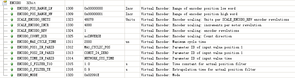
4.3 Virtual Encoder的参数设定
16-bit counters:
ENCODO_POS_RANGE_LW(ID1308): 0x00010000
ENCODO_POS_RANGE_HW(ID1309): 0x00000000
32-bit counters:
ENCODO_POS_RANGE_LW(ID1308): 0x00000000
ENCODO_POS_RANGE_HW(ID1309): 0x00000001
ID1323:编码器转1Rev所得到的量程单位unit (0.01mm=1unit)
ID1330:编码器1圈的Increment脉冲数
ID1324:编码器圈数
ID1325:编码器方向
由编码器的分辨率可以知道ID1324=1Rev则ID1330=4000 Inc。
经过测量或机械参数可以知道编码器一圈,输送带会移动460.78mm。
量程单位设为0.01mm=1unit,故ID1323=460.78mm/0.01mm=46078 Unit。
根据输送带向前运行时,编码器计数是增加还是减少的来设定方向ncSTANDARD/ncINVERSE。
本次应用时输送带向前运行时,编码器计数是减少的,因此ID1325=ncINVERSE。
ID1311:不清楚如何确定,现设定为2000us(2 POWERLINK + 50 us tolerance are set as the boundary for cycle time monitoring)
ID1312=MA1_CYCLIC_POS (ID542 此次的编码器是单圈,32位量程范围)
ID1313=CONST_I4_ZERO (ID292 此次的编码器是单圈,32位量程范围,因此设定为0)
ID1314=NETWORK_SYS_TIME(ID1194 使用本伺服的网络系统时钟)
ID1315=1.0sec 滤波时间,此次应用是输送带的速度同步,不需要位置精度,因此设得偏大
ID1315=0.9sec 预测时间,此次应用是输送带的速度同步,不需要位置精度,因此设得偏大
Virtual Encoder: Mode
Bit 0..7 = 0x1E: External position information mode
Bit 08: Extrapolation mode active
Bit 11: Interpolation mode active
Bit 17: Incremental encoder
ID1315 =0x02091E=2#10 0000 1001 0001 1110
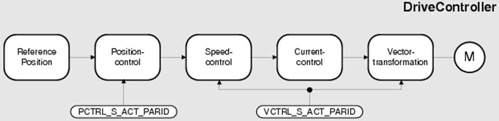
5. Encoder Link
5.1 Why need Encoder Link
当使用双编码器控制的时候,需要设定位置环和速度环实际所映射的编码器参数ID。
此次应用是通过位置环和速度环编码器参数ID的映射,在PLC里可以直接读取被动电源轴结构里的位置和速度,而此两个数据就是对应输送带移动的距离和速度。
pAxisDat->monitor.s; /*位置 0.01mm */
pAxisDat->monitor.v; /*速度 0.01mm/sec */
可以省去通过功能块或其他方法读取虚拟编码器的位置值和再进行运算而得到输送带速度。
5.2 Encoder Link参数ID
Parameter ID |
Access |
Data |
Value |
Init |
Unit |
Description |
name |
type |
range |
value |
|||
VCTRL_S_ACT_PARID |
RD,WR |
UI2 |
<ParID> |
std |
ParID |
Vector controller: Actual encoder position parameter ID |
PCTRL_S_ACT_PARID |
RD,WR |
UI2 |
<ParID> |
std |
ParID |
Position loop controller: Actual position parameter ID |
5.3 Encoder Link参数设定

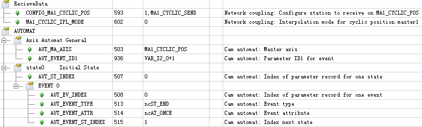
6. 主轴把ENCOD0_S_ACT_FILTER发送到网络上
![]()
7. 从轴从网络上接收ENCOD0_S_ACT_FILTER并使用