•The BOOL variables from the digital inputs are packed into a UDINT variable.
•The UDINT variable is mapped to a POWERLINK broadcast channel.
•Use the function plAction(), actionID = plACTION_GET_DP_INFO and both "DeviceName" and "ChannelName" to determine the node number of the transmitter (PLC) and the offset of the data that should be read by the drive.
•Determine the offset that is a multiple of 32 and makes it possible for the drive to access the data from the input channels (→ Integer arithmetic →Offset_ACOPOS = Offset / 32 * 32). It may be necessary to configure multiple receive channels on the drive depending on which channels of the input modules are being used. → Step 6 must be repeated accordingly.
•"DataType": For positions or signed values use ncPAR_TYPE_DINT; for status information, etc. always use ncPAR_TYPE_UDINT.
•Specify the offset from step 4 for the function block and then execute the function block.
•Map the "ReceiveParID" to a BIT SPT function block instance and extract the data.
Example:
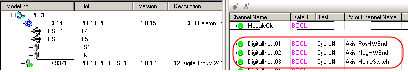
The positive hardware limit switch, negative hardware limit switch and reference switch of an ACOPOSmulti axis are connected to an X20 input card. The X20 input card is inserted in the X20 CPU that is the managing node of the POWERLINK network where the ACOPOSmulti drive is operated. The inputs should automatically be transmitted to the ACOPOSmulti drive and mapped to the axis.
I/O mapping of the DI card:
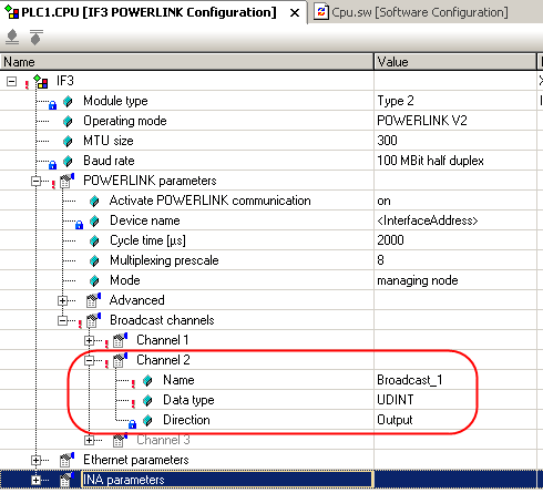
Creating a POWERLINK broadcast channel for the UDINT variable:
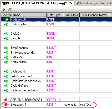
Mapping the UDINT variable to the POWERLINK broadcast channel:
Packing the BOOL DI variables into the UDINT variable (code must be called cyclically):
Axis1DIs := 0;
Axis1DIs := Axis1DIs + SHL(BOOL_TO_UDINT(Axis1PosHWEnd), 0);
Axis1DIs := Axis1DIs + SHL(BOOL_TO_UDINT(Axis1NegHWEnd), 1);
Axis1DIs := Axis1DIs + SHL(BOOL_TO_UDINT(Axis1HomeSwitch), 2);
Determining the bit offset:
PlActionGetDPInfo.DeviceName := ADR('IF3');
PlActionGetDPInfo.ChannelName := ADR('Broadcast_1');
plActionStatus := plAction(0,plACTION_GET_DP_INFO,ADR(PlActionGetDPInfo),SIZEOF(PlActionGetDPInfo));
Function block call:
MC_BR_InitReceiveNetworkData_0.Axis:=axis1Ref;
MC_BR_InitReceiveNetworkData_0.NodeNumber:= PlActionGetDPInfo.SrcNode;
MC_BR_InitReceiveNetworkData_0.BitOffset:=
(PlActionGetDPInfo.OffsetAbs / 32) *32; (* determine bit offset in multiples of 32 bits *)
MC_BR_InitReceiveNetworkData_0.DataType:=ncPAR_TYP_UDINT;
MC_BR_InitReceiveNetworkData_0.InterpolationMode:=mcIPL_OFF;
MC_BR_InitReceiveNetworkData_0.ReceiveChannel:=1;
MC_BR_InitReceiveNetworkData_0.Execute:=TRUE;
MC_BR_InitReceiveNetworkData_0();
Mapping the ACOPOS DI ParIDs to the received data:
A BIT SPT function block is configured so that the individual bits of the received data (transmitted digital inputs) are available as ParIDs. These ParIDs are mapped to the "ParID pointers" for the ACOPOS digital inputs.
ParID |
Value |
ACP10PAR_FUNCTION_BLOCK_CREATE |
ACP10PAR_BIT_MODE+0 |
ACP10PAR_BIT_A1+0 |
1 |
ACP10PAR_BIT_A2+0 |
1 |
ACP10PAR_BIT_A3+0 |
1 |
ACP10PAR_BIT_B1+0 |
(PlActionGetDPInfo.OffsetAbs MOD 32) |
ACP10PAR_BIT_B2+0 |
(PlActionGetDPInfo.OffsetAbs MOD 32)+1 |
ACP10PAR_BIT_B3+0 |
(PlActionGetDPInfo.OffsetAbs MOD 32)+2 |
ACP10PAR_BIT_IN1_PARID+0 |
MC_BR_InitReceiveNetworkData_0.ReceiveParID |
ACP10PAR_BIT_IN2_PARID+0 |
MC_BR_InitReceiveNetworkData_0.ReceiveParID |
ACP10PAR_BIT_IN3_PARID+0 |
MC_BR_InitReceiveNetworkData_0.ReceiveParID |
ACP10PAR_BIT_MODE+0 |
10 (extract from right) |
ACP10PAR_POS_LIMIT_SWITCH_PARID |
ACP10PAR_BIT_VALUE1+0 |
ACP10PAR_NEG_LIMIT_SWITCH_PARID |
ACP10PAR_BIT_VALUE2+0 |
ACP10PAR_REFERENCE_SWITCH_PARID |
ACP10PAR_BIT_VALUE3+0 |
Table: Parameter list