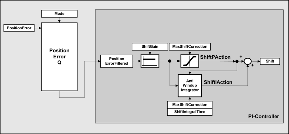
The controller structure in the image shows the path from the "PositionError" input value to the "Shift" output value.
The controller structure for the path from the "LengthError" input value to the "Distance" output value is the same; the corresponding controller parameters take effect in this case ("DistanceGain", "MaxDistanceCorrection", "DistanceIntegralTime").
•In a single application, only one of the two outputs "Shift" and "Distance" can be applied to the system. Applying both at the same time results in overcompensation of the measured deviation.
•When the "LengthError" is controlled, an integrator should not be used ("DistanceIntegralTime" should be 0) since application of a changed length with "Distance" already works like an integrator.
•The controller adjustment is calculated entirely on the target system. The function block must therefore be called at least two times per product length.