Immediately after the "Enable" input is set to TRUE, the function block status becomes "Busy = TRUE". The "Active" output is set after the parameters are successfully transferred.
If a signal to start the coupling (e.g. "LeadInSignal = TRUE") is received, the "InSync" output is set to TRUE if the lead-in movement is ended and the slave axis is coupled with the master axis via the cam.
If the coupling is disengaged by a "LeadOutSignal", "InSync" is reset when "MasterLeadOutOffset" is reached.
If the coupling is aborted (e.g. by calling MC_Stop), "Busy", "Active" ("DataInitialized" if applicable) and "InSync" are set to FALSE and "CommandAborted" is set to TRUE.
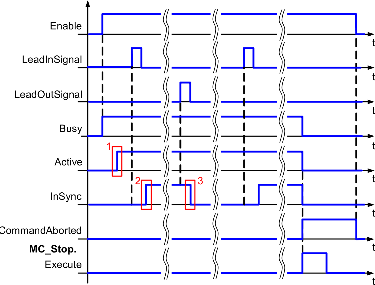
1 |
Parameter transfer completed |
2 |
Lead-in movement completed |
3 |
LeadOutMasterOffset reached |