This function block starts a cyclically repeating cam compensation sequence between the master and slave axis with an optional lead in and lead out.
Requirements for use
•This function block can only be used on SG4 target system.
•This coupling can only be started if the master axis is moving in the positive direction!
•When this function block is active, it is not permitted to change the length of the cam specified with "CamTableID" on the master or slave side or to delete the cam data module.
•It is not permitted to home the specified axis while the function block is active.
Axis states of the slave axis in which this function block can be used:
Function block
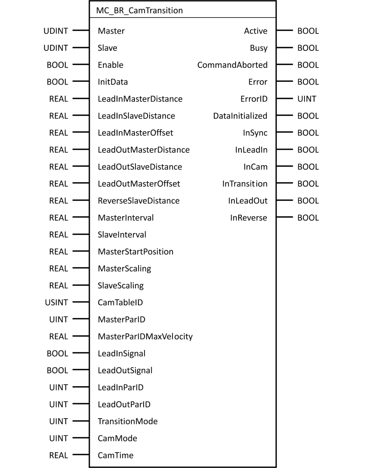
Parameter
I/O |
Parameter |
Data type |
Description |
IN |
Master |
UDINT |
Master axis reference |
IN |
Slave |
UDINT |
Slave axis reference |
IN |
BOOL |
The function block is active as long as this input is set. |
|
IN |
InitData |
BOOL |
Initializes input data on a rising edge (online change of function block input data) |
IN |
LeadInMasterDistance |
REAL |
Compensation distance of master axis for the lead-in movement [PLCopen units of master] |
IN |
LeadInSlaveDistance |
REAL |
Compensation distance of slave axis for the lead-in movement [PLCopen units of slave] |
IN |
LeadInMasterOffset |
REAL |
Offset on the master side within the cam. The compensating movement for the lead-in movement leads to this position [PLCopen units of master] |
IN |
LeadOutMasterDistance |
REAL |
Compensation distance of master axis for the lead-out movement [PLCopen units of master] Note: This is not permitted to be negative. |
IN |
LeadOutSlaveDistance |
REAL |
Compensation distance of slave axis for the lead-out movement [PLCopen units of slave] |
IN |
LeadOutMasterOffset |
REAL |
Offset on the master side within the cam. The compensating movement for the lead-out movement starts at this position [PLCopen units of master] |
IN |
ReverseSlaveDistance |
REAL |
No function at this time |
IN |
MasterInterval |
REAL |
Interval of the master axis (defines the master length of cam + compensation and the starting interval) [PLCopen units of master] |
IN |
SlaveInterval |
REAL |
Interval of the slave axis (defines the slave length of cam + compensation) [PLCopen units of slave] |
IN |
MasterStartPosition |
REAL |
Position within the period of the master axis or absolute position on a non-periodic master axis for beginning the cam [PLCopen units of master] Note: If "MasterParID" is used, no new value is calculated internally when restarting. This means that if the master position can overflow from the positive to the negative range of values, this value should be recalculated before each start. Otherwise, it is possible that re-coupling will not take place until the positive master start position is reached. |
IN |
MasterScaling |
REAL |
Master scaling factor for the cam (only evaluated in CamMode mcDISTANCE_BASED) |
IN |
SlaveScaling |
REAL |
Slave scaling factor for the cam |
IN |
CamTableID |
USINT |
ID number of the cam, output from MC_CamTableSelect or mcLINEAR_CAM Note: When this function block is active, it is not permitted to change the length of the cam specified with "CamTableID" on the master or slave side or to delete the cam data module. |
IN |
MasterParID |
UINT |
This ParID is used instead of the position setpoint; 0…Use position setpoint Note: When using a value other than 0 (even if the position ParID), the PLCopen factor of the master axis is not applied to any of the parameters involving the master axis. |
IN |
MasterParIDMaxVelocity |
REAL |
Prior to V2.290: Maximum speed of the master ParID value, only evaluated if the MasterParID is used
V2.290 and higher: If this parameter is "0.0", the current velocity of the master axis is used If a value is specified for "MasterParID": Maximum velocity of the master ParID value If a value is not specified for "MasterParID": Maximum velocity of the master axis [PLCopen units of master/s] Note: This value is used to calculate the compensating movement for coupling, changing the gear ratio or cams as well as between the cutting areas (depending on the function). This parameter has a considerable effect on the occurrence of ACOPOS error 37113: "Cam compensation gear: Limit values exceeded". No value specified: A master speed that changes or a parameter update via "InitData" or "Execute" can result in different, automatically calculated motion profiles. Value specified: Specifying the maximum speed value of the master axis that is achieved while coupled to the slave axis results in a motion profile that is always automatically calculated the same. |
IN |
LeadInSignal |
BOOL |
Signal from the controller to start the lead-in movement |
IN |
LeadOutSignal |
BOOL |
Signal from the controller to start the lead-out movement |
IN |
LeadInParID |
UINT |
ParID that can be used by the drive to start the lead-in movement when the value changes from 0 to a value ≠ 0 |
IN |
LeadOutParID |
UINT |
ParID that can be used by the drive to start the lead-in movement when the value changes from 0 to a value ≠ 0 |
IN |
TransitionMode |
UINT |
Mode for compensation phases: mcTRANSITION_OFF ... 0 mcTRANSITION_ON .... 1 + mcLEAD_IN ........ 2 + mcLEAD_OUT ....... 4 |
IN |
CamMode |
UINT |
Mode for synchronous curve: mcDISTANCE_BASED ... 0 mcTIME_BASED ....... 1 |
IN |
CamTime |
REAL |
Time for the synchronous curve [s] (only evaluated in CamMode mcTIME_BASED ....... 1) |
OUT |
Active |
BOOL |
Function block active, possible to execute movements Function block waiting for a lead-in signal |
OUT |
Busy |
BOOL |
The function block is active and must continue to be called. |
OUT |
CommandAborted |
BOOL |
Function block aborted by another function block |
OUT |
Error |
BOOL |
Error during execution |
OUT |
ErrorID |
UINT |
|
OUT |
DataInitialized |
BOOL |
Changes to function block inputs initialized |
OUT |
InSync |
BOOL |
Coupling established with master (after the start signal, the automat is no longer in the base or waiting state) |
OUT |
InLeadIn |
BOOL |
Coupling in the lead-in phase |
OUT |
InCam |
BOOL |
Coupling in the cam phase |
OUT |
InTransition |
BOOL |
Coupling in the transition phase |
OUT |
InLeadOut |
BOOL |
Coupling in the lead-out phase |
OUT |
InReverse |
BOOL |
No function at this time |
Table: Parameter MC_BR_CamTransition
Topics in this section: