"TriggerInput.EventSourceParID" is used to inform the function block about the source of the signal to which the registration mark position should be captured. For example, if the registration mark sensor is connected to the input Trigger 1 of the axis, then the ParID ACP10PAR_STAT_TRIGGER1 must be used.
Only ParIDs of data type INTEGER are allowed (no float values) for the "TriggerInput.EventSourceParID" input.
"TriggerInput.PosSource" can be used to configure whether the position setpoint or the actual position of the axis should be captured when the signal arrives from the registration mark sensor.
The registration mark position captured on the drive depends on the settings in "TriggerInput.Edge". The registration mark position can be applied during the contrast transition on the rising edge ("TriggerInput.Edge = mcP_EDGE") or falling edge ("TriggerInput.Edge = mcN_EDGE").
If width monitoring is enabled ("TriggerInput.MaxWidth > 0"), "TriggerInput.Edge = mcMIDDLE" (detection of the middle position between the rising and falling edge) is also possible.
A tolerance can be defined for the width of the registration mark by setting "TriggerInput.MinWidth" and ".TriggerInput.MaxWidth" in order to prevent false triggering when multiple trigger signals occur within the trigger window (width evaluation).
A trigger window can be defined around the expected position ("ProductParameters.RegMarkPosition") using "TriggerInput.WindowNegative" and "TriggerInput.WindowPositive". This value can be specified symmetrically ("WindowNegative" = "WindowPositive") or asymmetrically ("WindowNegative <> "WindowPositive").
This window can be used to filter invalid trigger signals from the sensor if multiple contrast differences are detected by the sensor within one interval, for example. The window should not be defined as too small, however, since this could cause the registration mark to quickly fall outside of the trigger window when dealing with larger material tolerances.
When using width detection, the window must be large enough for both edges to appear inside of it. Otherwise, the registration mark will be evaluated as invalid.
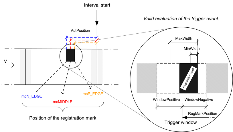
Fig.: "TriggerInput"
A certain time is needed for the registration mark sensor to complete the measurement process for detecting contrast differences (delay time). This is usually specified in the sensor's data sheet. If the value is configured (with negative sign) in line with the specification from the data sheet under "TriggerInput.SensorDelay", then the delay time of the sensor will be compensated for. This produces more exact measurement results. The value can be set to 0 to ignore the sensor delay time.
The larger the delay of the sensor for detecting the registration mark, the larger the interval between the detected trigger and actual occurring signal (depending on the speed of the transport axis, this significantly affects the calculation of the absolute position).
The drive performs internal linear reverse calculations to more accurately determine the absolute position of registration marks; as a result, movement speed should be as constant as possible near the position of the registration mark in cyclic operation. The same is true for the interval start, which should ideally be measured at a standstill (intermittent machine).
These measures contribute to the reduction of measurement errors and can have a decisive influence on the accuracy of registration mark control!
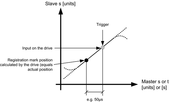
Fig.: Registration mark control
More calculation errors could therefore occur when the direction or slope changes at higher speeds:
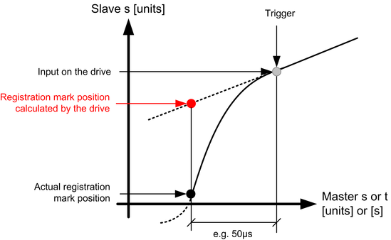
Fig.: Registration mark control computing errors