This function block starts a coupling between the master and slave axis similar to the MC_BR_CamDwell function block. The difference is that a cam does not have to be specified for MC_BR_AutoCamDwell. The slave drive uses the parameters to calculate a jerk-minimized motion profile (automatically calculated cam) with respect to the master movement.
This function block has the following functions:
•A standstill phase can be defined after the automatically calculated cam by setting "MasterDwellDistance > 0". This results in the following movement sequence: Cam – Standstill – Cam – Standstill – …
•A lead-in or lead-out movement can be started while the master axis is running. The slave axis does not move before the lead-in or after the lead-out movement.
•A compensation distance can be specified for the lead-in and lead-out movement.
Setting the "Enable" input switches the axis to the PLCopen Synchronized Motion state and transfers all necessary parameters to the respective drives.
The "Active" output is set after the parameters have been transferred. In this way, the coupling can be started when the "LeadInSignal" input is set or the ParID specified for "LeadInParID" changes from 0 to a value ≠ 0.
The movement can be stopped when the "LeadOutSignal" input is set or the ParID specified for "LeadOutParID" changes from 0 to a value ≠ 0.
If the "Enable" input is set to FALSE, the movement is stopped and the axis changes to the PLCopen axis state Standstill.
The automatically calculated cam can be shifted on the master side with the MC_Phasing or MC_BR_Phasing function block.
An offset shift on the slave side can be implemented using the MC_BR_Offset function block.
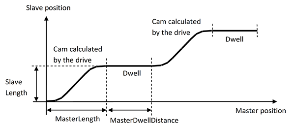
After the lead-in signal, the slave axis carries out a cam movement followed by a standstill phase. The master and slave side length for the automatically calculated cam can be defined using the "MasterLength" and "SlaveLength" inputs. The form of the cam is determined by the drive using the parameter settings. The duration of the standstill phase of the slave axis can be specified using the "MasterDwellDistance" input. This movement is repeated until the "LeadOutSignal" input is set or the ParID specified for "LeadOutParID" has a value ≠ 0.